What is a TankTop?
The Atkinson TankTop Offtake is an innovative solution for extracting oil or fuel from both above-ground and underground tanks. Top offtake systems incorporating an anti siphon valve are recognised as a “best practice” by the Environment agency. OFTEC, the regulatory authority for the oil heating industry, uses Building regulations and BSI standards as a frame work for installs, all of which advocate for best practice solutions where possible. The TankTop ensures safe and efficient fuel extraction.
The first complete tank top outlet solution incorporating an Anti-Siphon valve, floating suction, filter and outlet. This complete solution makes for a simple install and ticks all the boxes that might be required for your heating tank system.
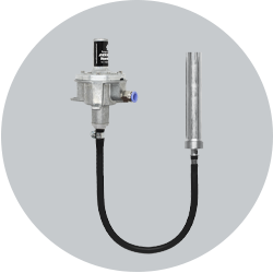
Important Features
Anti Siphon Protection – Factory set as standard 150mb/1.6m negative head, 50MB-450MB upon request
Oil Filtration – 50 Micron Filter
Clean Oil Intake – Floating Suction Hose
Push Fit Connection (10mm)
Why choose a TankTop over a bottom outlet?
If you’re new to to offtake solutions, you might wonder why you’d opt for one instead of traditional bottom outlets like the Atkinson Tankmaster or other bottom outlet valves. Here’s why the Atkinson TankTop Offtake is the preferred choice for installers:
1. Anti-Siphon Protection:
A key advantage of the TankTop Offtake is its anti-siphon protection. Bottom outlets rely on gravity flooded suction to supply the fuel which in the case of a leak would continue to spill, causing serious environmental damage and hefty fines under the Control of Pollution Act 1974. Plus, losing a full tank of oil or fuel is expensive! The TankTop prevents this scenario entirely, which is why OFTEC considers it “best practice.”
2. Clean Supply with Floating Suction:
The TankTop’s unique floating suction feature ensures that only the cleanest layer of oil is drawn into the line, leaving heavier particles and contaminants at the bottom of the tank. Traditional bottom outlets pull fuel from the bottom, where debris tends to collect. The TankTop filters this top layer of oil through a 50-micron filter, ensuring a cleaner, more efficient supply. This is a significant advantage for maintaining the longevity of equipment and minimizing maintenance issues.
3. No Compromise to the Secondary Bund:
With the TankTop Offtake, the tank’s bund – a secondary containment system – remains uncompromised. Bunded tanks, which are essentially tanks within tanks, provide an extra layer of protection in case of leaks. Bottom outlets must pierce both layers of the bund, which negates the benefit of a contained bund system. In contrast, the TankTop extracts fuel from the top of the tank, reducing the risk of leaks and maintaining the bund’s effectiveness. This design feature further enhances the TankTop’s reputation as one of the safest options on the market.
4. Ease of Replacement and Maintenance:
Being a top outlet, the TankTop Offtake makes maintenance much easier. If you ever need to replace or service the unit, you don’t need to drain the tank or wait until it’s empty, unlike with bottom outlets. With bottom outlets, you might require a fuel transfer kit or another tank to hold the contents during maintenance, and if the isolation valve has seized over time, you’re left with no easy solution. The TankTop, by contrast, relies on diaphragms and siphoning, meaning its components are far less likely to seize compared to lever or union valves, providing you with reliable long-term operation.
For installers, the TankTop Offtake offers not only increased safety and reliability but also practical benefits that make maintenance and service much simpler. By choosing the TankTop, you’re ensuring a higher standard of safety, cleanliness, and ease of use for your customers.
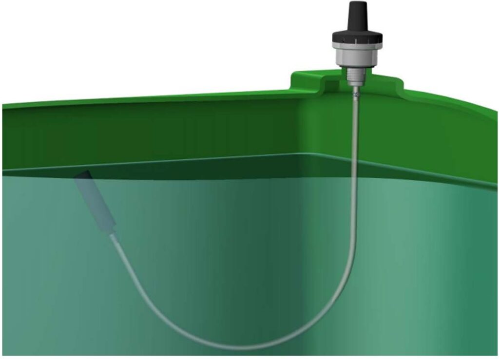
Image: Installation example view.
How does it work?
In a top offtake negative pressure applied from the system pulls oil or fuel from the suction hose into the line. Once the fuel passes down again past the point of the fuel level inside the tank gravity helps create a siphoning effect. This allows the fuel’s weight to generate positive pressure, pushing it further through the line and continually pulling from the tank.
As the Tanktop incorporates an anti-siphon valve this provides resistance against the line with the idea being this resistance is set to a higher level than the drop in the pipework. This means it is the appliance/system that needs to create suction to open the valve. If set correctly a leak in the line will not be enough to overcome the anti-siphon valve and pull oil from the tank. The negative pressure, introduced by the pump in the appliance through the inlet, moves into the diaphragm chamber, pulling it down along with the axle. This opens the valve near the hose tail, which happens only when the negative pressure reaches a certain level (usually factory-set at 150 millibar or up to 450 millibar by request).
When the valve opens, the negative pressure pulls the fuel past the non-return valve, through the centre of the axle, and out through the filter and outlet. As the fuel level at the outlet drops below the inlet, a siphon forms, continuously drawing fuel from the tank. The weight of the fuel helps turn the negative pressure into positive pressure, pushing the fuel through the line.
NB: The anti siphon setting is resistance in the line equivalent to a lift in the line. In order to create the suction necessary either a Tigerloop or oil lifter should be fitted. This will depend on the appliance(i.e. pressure jet boiler or range cooker) and the lift and run between tank and the appliance.
Fitting the TankTop
IMPORTANT: THE TANKTOP MUST BE FITTED IN CONJUNCTION WITH A DEAERATOR OR AN OIL LIFTER
Fitting on a Plastic Tank
(If the plastic tank has a moulded 1” insert, use the steel tank fitting instructions above).
1. Drill a 30mm hole in a flat area on top of the primary tank.
2. Thread the float and suction pipe through the 30mm hole.
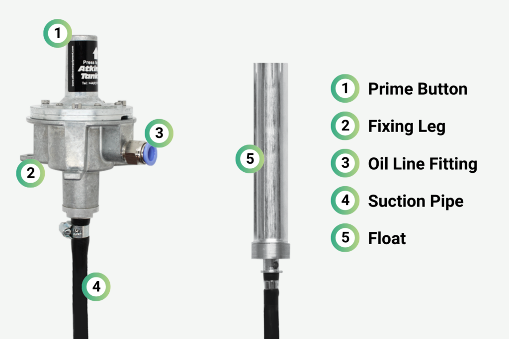
3. Orientate the 10mm hydraulic or compression fitting to the desired pipe direction, screw the 3 legs down with the screws provided.
4. Cut the 10mm oil line to be used, with a tube cutter NOT a hacksaw.
5. Insert the 10mm pipe into the hydraulic or compression fitting (if using compression fittings make sure a support tube is used) making sure the pipe is fully home.
6. Having fitted all ancillary equipment in the line (using support tubes in all joints) to the pressure jet burner (including a de-aerator and the bypass screw in the burner pump) fire up the burner. The burner should be able to pull the fuel through but if the pipe is long with a lift to the burner the prime button can be pressed whilst the burner is running to open all the Tanktop valves. This will bypass the anti-siphon valve making it easier for the burner to prime the line.
MAX/MIN LINE TESTING PRESSURE +0.5/-0.6 BAR
TIP: Always use 10mm support tubes TM4172 inside soft copper oil lines to ensure air tight joints when using compression joints.
Fitting on a Steel Tank
1. With the back nut still on, dress the Tanktop 1” BSP thread with PTFE tape. Thread the float and suction pipe through the 1” BSPP nipple on the top of the tank and screw home.
2. Position the Tanktop so the oil line fitting is pointing in the desired direction and nip the back nut down onto the tank nipple.
3. Cut the 10mm oil line to be used, with a tube cutter NOT a hacksaw.
4. Insert the 10mm pipe into the hydraulic 10mm fitting or compression fitting (if using compression fittings make sure a support tube is used) making sure the pipe is fully home.
5. Having fitted all ancillary equipment in the line (using support tubes in all joints) to the pressure jet burner (including a de-aerator and the bypass screw in the burner pump) fire up the burner. The burner should be able to pull the fuel through but if the pipe is long with a lift to the burner the prime button can be pressed whilst the burner is running to open all the Tanktop valves. This will bypass the anti-siphon valve making it easier for the burner to prime the line.
Warranty Terms
The TankTop comes with a 36-month return-to-supplier warranty, covering defects and issues not related to specific serviceable parts.
Serviceable items, listed below, are only covered by a 6-month warranty:
- Suction Hose
- Non-Return Valve Ball
- Diaphragm
- Seals, such as O-Rings
Note: Any components made of rubber or a combination of Nitrile/PVC fall under this category.
The warranty does not cover damage caused by negligence, improper use, incorrect installation, or using the product outside its intended purpose or industry.
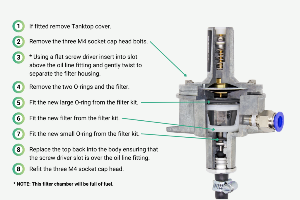
Replacing the TankTop filter
